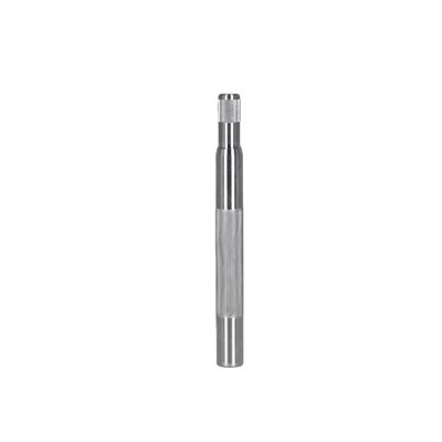


Torsional stiffness is a crucial mechanical property of a motor shaft, which significantly impacts the performance and reliability of motors. As a motor shaft supplier, understanding how to calculate the torsional stiffness of a motor shaft is essential for providing high - quality products to our customers. In this blog, we will delve into the principles, methods, and factors related to calculating the torsional stiffness of a motor shaft.
Understanding Torsional Stiffness
Torsional stiffness, denoted as (K_t), is defined as the ratio of the applied torque (T) to the resulting angular deformation (\theta) in radians. Mathematically, it can be expressed as (K_t=\frac{T}{\theta}). A higher torsional stiffness means that the shaft can resist more torque with less angular deformation. This property is vital in motor applications because excessive angular deformation can lead to misalignment, reduced efficiency, and even mechanical failure.
Basic Formula for Torsional Stiffness
For a solid circular shaft, the torsional stiffness can be calculated using the following formula:
[K_t=\frac{GJ}{L}]
where:
- (G) is the shear modulus of the material. The shear modulus represents the material's resistance to shear deformation. Different materials have different shear moduli. For example, steel typically has a shear modulus (G) of about (79\times10^9) Pa, while aluminum has a shear modulus of approximately (26\times10^9) Pa.
- (J) is the polar moment of inertia of the cross - section of the shaft. For a solid circular shaft with a diameter (d), the polar moment of inertia is given by (J = \frac{\pi d^4}{32}).
- (L) is the length of the shaft.
Let's take an example. Suppose we have a solid steel motor shaft with a diameter (d = 0.05) m and a length (L=0.5) m. The shear modulus of steel (G = 79\times10^9) Pa. First, we calculate the polar moment of inertia:
[J=\frac{\pi(0.05)^4}{32}\approx6.14\times10^{-8}\ m^4]
Then, we can calculate the torsional stiffness:
[K_t=\frac{GJ}{L}=\frac{79\times10^9\times6.14\times10^{-8}}{0.5}\approx9669.2\ N\cdot m/rad]
Impact of Shaft Geometry
The geometry of the shaft has a significant impact on its torsional stiffness. As we can see from the formula (K_t=\frac{GJ}{L}), the polar moment of inertia (J) plays a crucial role. For non - circular cross - sections, the calculation of (J) becomes more complex. For example, for a hollow circular shaft with an outer diameter (D) and an inner diameter (d), the polar moment of inertia is (J=\frac{\pi(D^4 - d^4)}{32}).
A hollow shaft can be more efficient in terms of weight and material usage while maintaining a relatively high torsional stiffness. If we compare a solid shaft and a hollow shaft of the same outer diameter and length, the hollow shaft can have a similar torsional stiffness with less material. This is because the material near the center of the shaft contributes less to the torsional resistance, and removing it can reduce the weight without sacrificing much stiffness.
Material Selection
The choice of material is also a key factor in determining the torsional stiffness of a motor shaft. As mentioned earlier, different materials have different shear moduli. For applications where high torsional stiffness is required, materials with high shear moduli, such as steel, are often preferred. However, other factors such as cost, weight, and corrosion resistance also need to be considered.
For example, in some lightweight applications, aluminum may be a better choice despite its lower shear modulus. Aluminum is lighter than steel, which can reduce the overall weight of the motor. In addition, aluminum has better corrosion resistance in certain environments.


Practical Considerations in Calculation
In real - world applications, there are several factors that need to be considered when calculating the torsional stiffness of a motor shaft.
- Load distribution: The applied torque may not be uniformly distributed along the shaft. For example, in a motor with multiple gears or pulleys, the torque may vary at different positions along the shaft. In such cases, a more detailed analysis using finite element analysis (FEA) may be required.
- Boundary conditions: The way the shaft is supported at its ends can affect the torsional stiffness. For example, a shaft with fixed - fixed boundary conditions will have a different torsional stiffness compared to a shaft with one end fixed and the other end free.
- Dynamic effects: In high - speed motor applications, dynamic effects such as vibration and resonance need to be considered. These effects can cause additional stresses and deformations in the shaft, which may affect its torsional stiffness.
Our Product Offerings
As a motor shaft supplier, we offer a wide range of motor shafts to meet different customer needs. Our product portfolio includes Threaded Shaft, Commercial Motor Shaft, and Fan Motor Shaft.
Our threaded shafts are designed for applications where easy installation and connection are required. They are available in different thread sizes and materials to ensure compatibility with various motor systems. Our commercial motor shafts are suitable for a wide range of industrial applications, providing high torsional stiffness and reliability. The fan motor shafts are specifically designed for fan applications, with optimized geometry and material selection to ensure efficient operation.
Contact Us for Purchase
If you are in the market for high - quality motor shafts, we invite you to contact us for a detailed discussion. We have a team of experienced engineers who can help you select the most suitable motor shaft for your application based on the required torsional stiffness and other performance requirements. Whether you need a standard product or a custom - designed shaft, we are committed to providing you with the best solutions.
References
- Beer, F. P., Johnston, E. R., Mazurek, D. F., & Cornwell, P. J. (2015). Mechanics of Materials. McGraw - Hill Education.
- Shigley, J. E., & Mischke, C. R. (2001). Mechanical Engineering Design. McGraw - Hill.